3D Printer (2/9/2014)
I've decided to build myself a 3D printer. All of the software (CAD, PC printer control, and printer firmware) are all available as open source downloads. So are the plans for many different printer designs. Most of this is part of the Rep Rap project (http://reprap.org/wiki/RepRap).
Many of the designs for 3D printers you find on line use plastic parts that are printed on a 3D printer. In other words, a 3D printer can actually print itself! (At least it can print the plastic parts. There are lots of metal parts too). That presents a bit of a chicken and egg problem, how can you download the part files and print them to build a printer if you don't already have one? There ARE kits of these parts available on ebay and elsewhere of course.
I decided to try and build my printer out of whatever I could fabricate myself using available tools. For me, this would mean using wood or metal, as I can do simple machine on either at home with some basic hand and machine tools. Various metal shapes are available at the local home improvement / hardware store, such as bar, angle, and rod stock in steel and aluminum.
Like many others who have built CNC machines, I decided to try using ball bearing drawer slides as linear bearings. These devices are actually very stable and move smoothly with little play and backlash so long as you don't try to use too much extension so that the weight bearing part of the slide is over-extended and not supported by any bearing surface. In other words, a 14" drawer slide can support a 7" wide bed with 7" of travel before it over extends and "hangs over" the bearing support. For this reason, I decided to make a machine with a 7" x 7" build area, as this is within the limits of the smallest available (and cheapest!) ball bearing drawer slide. I'll limit my vertical build height to 7" as well for the same reason.
As for method of construction, at this point I've decided on using steel angle bar stock and steel threaded rods to make the framework of the machine. Aluminum bar stock would be lighter, but would also flex more when built out of the same size as the steel. The steel is also slightly cheaper, though tougher to drill. That's no problem though with a drill press, good sharp bits, and cutting oil. Don't try drilling though steel bar stock without using 3-in-on oil or WD40 to lubricate the cut, or you will burn out your bits!
Most 3D printers use 4 or 5 stepper motors to drive the mechanics. There are several ways of moving the work area and the print head in relationship to each other. CNC machines often move the work platform in both the X and Y directions and lift the tool up and out of the way in the Z direction. This works out well for a CNC machine where the tool doesn't have to move much up and down, and the parts being machined are not very tall in height.
A 3D printer needs about the same freedom of movement in all three dimensions. Moving the work bed in only one direction requires a footprint of twice the build area for the machine, moving it in two dimensions requires a machine footprint of four times the build area. For this reason most 3D printer designs move the build bed only in the Y or Z dimension. I decided to use the most popular format for my machine. The build bed will move in the Y dimension, or forward and backwards. A "gantry" will hang over the bed in the X dimension. This gantry will move up and down in the Z dimension, and will carry the linear rails for the X axis. Riding along the X axis will be the carriage carrying the print head extruder.
The Y axis will be driven by a toothed belt and a pulley equipped stepper motor. The X axis will also be moved by the same kind of hardware. The gantry will be lifted in the Z axis by two threaded rods spun by two stepper motors. This is the most common kind of drive system used, though some printers will move the print head extruder in the X and Y dimensions and lift and lower the print bed in the Z. This makes for a smaller printer, but is a bit more complicated mechanically to build.
If you were counting, you see that requires a total of 4 stepper motors. Well there is 5th one required to operate the extruder. This motor pulls a filament of plastic through a heated nozzle to be melted and laid down, layer by layer, on our print bed to form the object being created. Stepper motors come in various sizes, but the most common ones used in printers and CNC machines are NEMA-17 or NEMA-23 in size. (Which are about 1.7" or 2.3" square respectively).
I bought 5 pieces of NEMA-23 sized motors at a ham radio flea market for $5 each. These are a bit larger and more powerful than required, but they should work and are (barely) within the power rating of the driver chips I'll be using.
The electronics controlling most 3D printers is based on the Arduino platform and use an Atmel AVR processor. The Arduino Mega board with a RAMPS shield is the most popular platform, and is the one I decided to use (I already had an Arduino Mega board). There are a few other single board controllers in use that you can build yourself or buy on ebay.
At this point I have my drive belts, pulleys, and stepper motor driver boards on order from ebay suppliers. I just got the RAMPS board in the mail yesterday.
I've started getting various metal hardware from the local HomeDepot to build the frame of the machine, and I'm still adjusting various ideas in my head. Once I have the print head carriage moving smoothly in the X and Z directions and the bed in the Y I'll worry about the extruder and hot end (that's the heated print nozzle), though I already have ideas for those almost figured out.
I've downloaded OpenScad which is an open source 3D cad program. It's not a WYSIWYG program, rather it uses a scripting language that resembles C or Python to describe the object being designed. The program does give you a visual view of the object in 3D so you can see what you've designed. There are other cad programs out there, including Google Sketchup (that one only works in windows and mac). Guess I should have mentioned I'm running Linux Mint on my computer.
I'll post pictures here once I actually start building.
Update: 3/2/2014
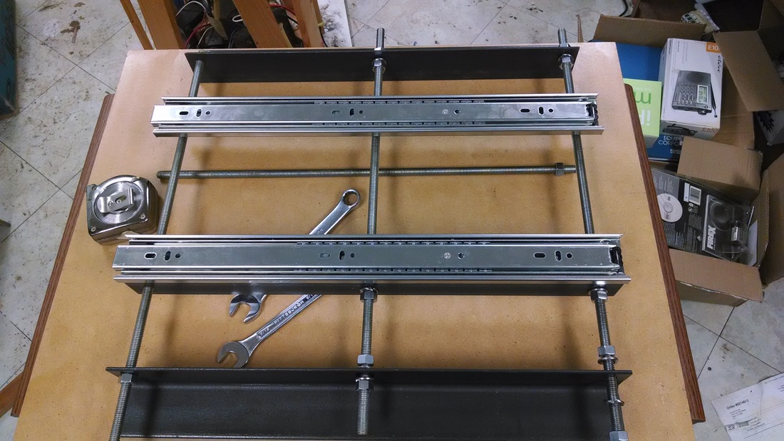
Dry fit of parts for the frame and Y-Axis
I've been cutting and drilling steel angle stock. Here are the two 2"x2"x18" side rails and 1.5"x1.5"x18" support rails for the linear slides. It's all held together by 3/8" threaded rod, not unlike the way RepRaps are built. This is a dry fit to get an idea of the parts placement. The drawer slides are attached to the support rails by a good quantity of #8 screws, lock-washers and nuts. Each threaded rod is attached to each steel angle by two nuts and two split lock-washers. The print bed will be a 9"x8" piece of 1/2" fiber board attached between the drawer slides. The center of the bed board will be cut out (hollow) to allow for ventilation of the heated bed assembly which will be a piece of 1/8" aluminum with a piece of sheet glass on top held on with bulldog clips. The bed will be heated by an assortment of junkbox 5W sand resistors glued to the plate with JB Weld, wired in series/parallel and powered by a 36 volt 6 amp surplus transformer. With the resistors I have in my junk box it will draw about 150W. The RAMPS board will drive a solid state relay to bang-bang control the primary of the bed transformer.
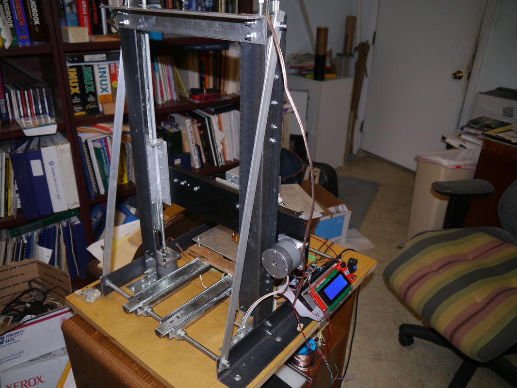
I still have to drill mounting holes for the side rails to attach them to the fiber board base. Then I need to cut two pieces of 2"x2"x24" steel angle to support the Z-Axis linear slides and build the gantry with the X-Axis linear slides. I can't mount the Z-Axis supports until I know exactly where they need to be to put the hot end over the Zero position with the Y-Axis at it's zero position. This means I need to have the design of my extruder figured out so I know the depth of the trolley that rides on the X-Axis.
I will also have to dry fit the mountings for the Z-Axis drive motors. These Nema-23 steppers will mount on the bottom of the Z-Axis like on the newer Prusa's and unlike the older Mendal's. You really DON'T want to have any weight hanging on those flexible shaft couplings, they tend to stretch out. I will have the tops of my drive screws hanging from 608 bearings to support the weight of the gantry, don't want to compress the springs on the stepper motor bearings!
SO...it seems that all the bits of my design are so inter-connected that I need to build everything at once to be able to dry fit that it all will come together correctly! ARGH! Well if I can get close enough on the gantry placement, the 18" long Y-Axis rails do give me a little bit of freedom. I now have 9" of usable travel (I was going to use the 14" rails but decided to go with the larger ones on the Y and Z axis's). So I will be able to hit my 7"x7" build platform size even if I miss on the placement of the gantry supports by an inch. I will also have at least 12" of travel in the Z axis, so I could build stuff that tall. I figured that since the 2"x2" steel for the supports was going to end up being 24" tall I might as well go with the 18" slides since I also had 24" 5/16" drive screws
Those 18" drawer slides don't seem as silky smooth in travel as the 14" ones were, but maybe some silicon lube will help. They're not really bad, just not as smooth as I'd like.
I'll post another photo update when things progress a bit more.....
Update: 3/16/2014
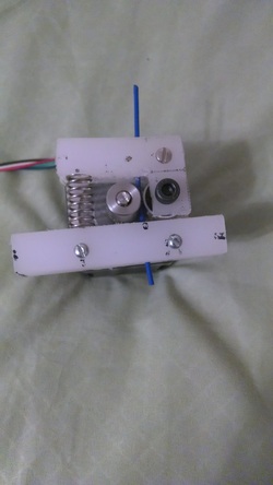
Not too much progress, but I now have an extruder.
I bought an MK7 drive gear off Ebay and cut some 1/2 thick plastic from an old cutting board. Turned out this stuff wasn't solid through and through, but rather 'airy' in the middle (50% fill in 3D printer terms). Still, it might be strong enough. Anyway, the design is quite similar to many on Thinkiverse, a lever arm presses a bearing idler wheel against the filament into the drive gear. The parts are screwed directly onto the front face of a NEMA-17 stepper motor. I got a pack of springs from HomeDepot and picked one that seemed to have about the right amount of tension for the job. The bearing is held in place by a M8 screw, the plastic is tapped to take the screw threads. I can easily turn the gear by hand with two fingers and it pulls the filament easily. Hopefully the motor will be strong enough. It's a 0.9 degree / step rated at 0.8 Amp at 7.5 ohm. Actually the coils are 15 ohms since they are run in series. At 12 volts we would just get the rated current. I might have to run the extruder at a higher voltage, or look for another motor. I could probably cut some traces on the RAMPS board to run just one of the stepper drivers at a higher voltage, placing a 12v 1A power supply in series with my main one.
I'm going to use 1.75mm filament. This choice was made for me by the selection of a low cost hot end kit from "ohioplastics" on ebay. His "J Head Lite" design is rather novel, and looks good. It seems that 1.75mm filament has a few advantages, one being that less force is required to extrude it through the hot end. This means the extruder needs less torque, and a direct drive unit using NEMA17 motors are quite possible. Bowden style extruders using 1.75mm filament are probably easier to get working than with 3mm as well. A quick check on Ebay and elsewhere showed me that availability and cost of the 1.75mm stuff is not an issue anymore. In fact, some specialty filament is ONLY available in 1.75mm.
I'm also going to start off with PLA, though I fully intend to be able to print with ABS as well. I have a design for a heated bed in the works (more on that in a future update).
Now that I know what my extruder is going to look like, and how much room it needs on the X carriage I can begin to layout the placement of the X/Z axis gantry assembly. My wiring cables have come in and I will soon try testing the motors with my RAMPS and stepper drivers. I don't know if I can issue commands to stock firmware to test drive the steppers or if I'll just write a simple Arduino sketch.
Direct Drive Extruder
UPDATE: 5/15
Progress has been slow, and I've done some re-design. I'm probably going to re-write these pages with new photos and some information on my design for anybody that wants to copy it.
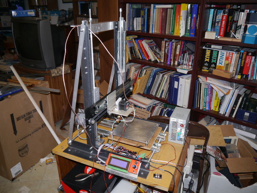
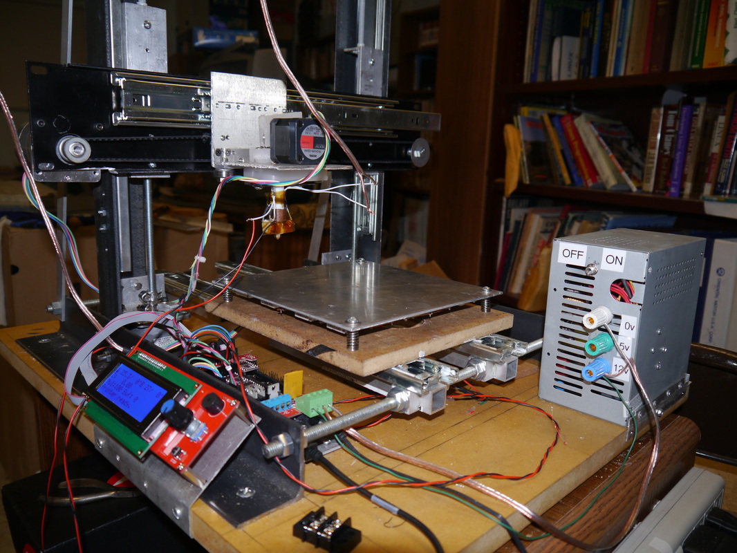
I've tested the direct drive extruder by hooking it up to my RAMPS board and controlling it from Repetier Firmware loaded onto the Arduino Mega. I may switch to the Marlin firmware a little later on, as I think it supports auto bed leveling better.
I've also modified an old PC power supply to power my printer.
This is a RepStrap BTW. That means it will be used to print parts to make another printer of a RepRap design. I've also given this machine a name.
The design will be called a "DepotStrap" since most of the hardware came from the HomeDepot. The machine's model name is "Cobalt", since this printer will be a prototype for the next one. (Cobalt was Astro Boy's brother, and was also Dr. Tenma's prototype for Astro.)
Progress has been slow, and I've done some re-design. I'm probably going to re-write these pages with new photos and some information on my design for anybody that wants to copy it.
I've tested the direct drive extruder by hooking it up to my RAMPS board and controlling it from Repetier Firmware loaded onto the Arduino Mega. I may switch to the Marlin firmware a little later on, as I think it supports auto bed leveling better.
I've also modified an old PC power supply to power my printer.
This is a RepStrap BTW. That means it will be used to print parts to make another printer of a RepRap design. I've also given this machine a name.
The design will be called a "DepotStrap" since most of the hardware came from the HomeDepot. The machine's model name is "Cobalt", since this printer will be a prototype for the next one. (Cobalt was Astro Boy's brother, and was also Dr. Tenma's prototype for Astro.)